Pulsed power technologies refer to power sources providing a huge amount of energy during very short times. These technologies have applications in various fields of science and engineering: production of transient electrical discharges and plasmas, generation of radiation and ions beams, high-density matter, production of pulsed high magnetic fields and shock waves. The achievements in those fields impact on various economic and industrial areas: electronics, microlithography, mining, medicine, agriculture, defense and materials, among others. Taking advantage of the experience in pulsed power technology obtained in the experimental researches in dense transient plasmas, an exploratory line of pulsed power applications is currently being developed.
Portable nanoflashes of radiation: high brightness UV, VUV, soft and hard X-rays, neutrons
The pulses of radiation (neutrons and x-rays) last a few nanoseconds; in particular, x-rays have a wavelength of nanometres or less. That is the reason we call them ‘nanoflashes’.
Small devices are not only interesting for pure plasma research but also for field applications. More remarkable is that it constitutes a safe radiation on–off source. A PF is especially suited for pulsed neutron applications with a reduced danger of contamination compared to conventional isotopic radioactive sources. A passive radioactive source of neutrons with similar energy (∼2.5 MeV; for instance
252Cf or Am/Be) emits continuously, with high risks in handling and storing. Of course, PF sources do not have such activation problems.
On the one hand, the intense x-ray pulses produced by bremsstrahlung radiation from localized electron beams and from hot spots are excellent candidates for radiography of moving or wet objects and for microelectronic lithography.

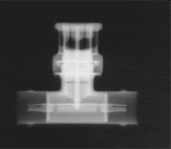
| Figure 1. X-ray image of a stainless steel BNC ‘T’ connector obtained with multiple shots using the PF-400J device at CCHEN. The average effective energy of the x-rays is ∼90 keV. The metalic internal structure is easily identified.
|
PF devices are being considered for applications in microlithography. One present challenge is to increase the spatial resolution. Two features determine the spatial resolution: the radiation wavelength λ and the source size. As far it is known, in small devices wavelengths are not different to those from larger devices. But, smaller PF could be advantageous because of the reduced size of the spot where radiation originates. In fact, the soft x-ray sources are inside the plasma pinch column corresponding to hot or bright spots which last nanoseconds or less. It has been shown that the plasma pinch column size linearly scales with the anode radius a, while the pinch radius is ∼0.12a and the pinch length is ∼0.8a. Therefore, in the worst case, the maximum size of a hot spot will not be greater than 0.24a. Similarly, the source size of hard x-rays will not be greater than 2a.
According to our results, a
3 scales in proportion to the device storage energy, E. The anode radius of a kJ device is of the order of 1 cm. Then, the maximum soft x-ray source size cannot exceed the pinch diameter: ∼2 mm. For a device of 1J the anode is of the order of 1mm and the maximum soft x-ray size source could not exceed the pinch diameter: ∼0.2 mm. Moreover, according to the observations in devices operating with energies from kJ to MJ, the bright spots have typical dimensions lower than 0.1 times the pinch diameter, i.e. 0.02a.
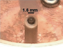
For the Nanofocus, the ultra miniaturized PF device we have developed, the anode diameter is 1.6 mm and the spot size is about 200 μm. This apparatus is currently under characterization as an ultra small radiation source, operating in a repetitive regime (0.1 J per shot).

| Figure 2. Spot on the anode of the Nanofocus device after about 1000 discharges. The spot is probably due to the erosion produced by the electron beams impinging on the anode and by the interactions of the plasma pinch. The diameter of the anode is 1.6 mm and the size of the spot is of the order of 200 μm.
|
On the other hand, the emitted neutrons could be applied to perform radiographs and substance analysis and detection, taking advantage of the penetration and activation properties of neutral radiation. Among others, a possible application is substance detection by means of neutron backscattering. This is obtained by using a PF device in repetitive mode. For example, a repetitive neutron pulsed generator (Hz to kHz) based on a very-low-energy plasma focus as the PF-50J developed at CCHEN can lead to a breakthrough in engineering applications, such as soil humidity measurements, medical neutron therapies, substance detection (explosives, drugs, minerals, etc) and others.
This feature is greatly facilitated by the lower energy required to produce neutrons. In fact, according to the available commercial information, fluxes of 10
6- 10
8 neutrons s
−1 are adequate for prompt gamma neutron analysis [1], and for detection of substances by means of neutron backscattering, 10
4–10
5 neutrons s
−1 are required [2]. A PF-50J operating at 1 kHz and 1 Hz, respectively, could be used for such kind of application.
For field applications, a portable device based on the Nanofocus is being developed. Evidence of neutron emission has been observed in this ultra miniaturized device, operating at 0.1J of stored energy and 20Hz of repetition rate. Up to date the reproducibility of this very small device is low and technological issues are currently under analysis in order to produce neutrons for periods greater than minutes.
In addition, a device with a stored energy between the boundaries of 50 and 0.1J is being explored. A compact, low-weight, portable PF device for field applications is being designed in detail. A device to be operated at a few kilovolts (10 kV or less) with a stored energy of 2 J and a repetition rate of 10 Hz without cooling is being designed.
Electrode erosion It is important to note that, in the PFR device, the erosion of the electrodes must be considered. This situation is being studied theoretically. A two-dimensional implicit finite element model has been implemented to solve Fourier’s second law of heat conduction in time and space. It considers a cylindrical geometry, so the three-dimensional domain of a real PF electrode can be considered only using the radial and axial coordinates. The plasma sheath that impinges on the surface of the electrode is considered as a moving heat source of given power density.
The power density is modelled by a correlation obtained somewhere else, and it becomes a function of the capacitor bank energy. The speed of the heat source moves along the z-axis in the upper direction and it is obtained by empirical observation of the motion of the plasma sheath. The model then gives as a result the thermal field in space and time during the plasma–electrode interaction time as well as during the cooling time until the next pulse takes place. After a certain train of pulses has taken place, one can then estimate the final temperature and compare it with the melting temperature of the material the electrode is made up of.
Higher temperatures than the melting temperature will mean the electrode has undergone melting and possible material ejection. The results of these calculations will be compared with experiments.
High pulsed magnetic field generation Present generation of powerful permanent magnet materials is based in rare-earth elements such as neodymium (Nd) and samarium (Sm), and transition metals like iron (Fe) and cobalt (Co). The magnetic properties are so remarkable that the rare-earth permanent magnets are also called ‘supermagnets’. The capacitor bank is composed of five 88 μF × 1200 V capacitors (i.e. a total capacity of 440μF). An additional 88 μF × 1200 V capacitor was acquired as supply element. To magnetize specimens of these materials, higher magnetic field strengths (of about 10 T) are required. The behaviour of a serial-RCL circuit used in magnetizers is well known. However, detailed design dimensionless relations have been obtained from this work. A final total electric resistance of about 152.5 m is expected. Then, a 0.69 ms width current pulse with a peak near (1540 ± 60) A is also expected, when the capacitor bank is charged at (950±35)V. This should correspond to a 10 T applied magnetic field strength at the centre of the specimen. These values will be tested when the magnetizer is completely built.
Rock fragmentation Copper mining and related industry in Chile play the most important role in the economy. International regulations are increasingly demanding the use of clean technologies in order to participate in world markets. Plasma blasting for rock fragmentation is an interesting possibility to replace traditional, environmentally degrading explosives.
Complementary to the experimental work, studies on material features are being developed. A new method for dealing with the mechanics of heterogeneous materials subjected to high stresses was introduced in the recent past by Lagos [3]. The method was applied in order to obtain the general properties of the deformation experienced by a polycrystalline solid when stressed beyond the elastic limits. The results of the theoretical treatment allow predicting, from the macroscopic mechanical properties of the material, whether the material will display a ductile, brittle or superplastic behaviour. Briefly, the action of the stress tensor on the random granular medium is analysed in detail, and it is shown that the trace of the resulting strain rate tensor, giving the time-dependent deformation, does not vanish in general. Then, deformation does not conserve density, and the grains are increasingly compressed as the sample is being stretched. The consequent internal pressure helps deformation and, under some precise physical circumstances, the sample becomes mechanically unstable and collapses. According to the material constants, the effect can explain extreme brittleness or large ductility.
At present, the activity is to considered the same scheme applied to rocks studies, esentially another class of highly heterogeneous solids. Rock inhomogeneities are often very irregular through the bulk and surfaces of the material. The objective is to determine the structural conditions for a rock to be brittle and practical ways to identify eventual weak zones in rocks, in order to break them with minimal energy. At this time, work is being done in theory, in order to determine what to search in actual rocks. However, experimental work in rock fracturation should be a complement to this work.
Small multipurpose bank A multipurpose bank of less than dI/dt ∼5.75×10
11 As
−1, 180kA) has been constructed [4]. This equipment will be used for the scaled experimental study of rock fragmentation and for Z-pinch experiments. Experiments on X-pinches are being planned. Electrodes identical to the ones used in the SPEED2 gas-embedded Z-pinch experiments will be used in the small multipurpose bank in order to study in detail the initial conditions and the early times of the discharges, complementary to the studies carried out in the SPEED2.
[1] All Russia Research Institute of Automatics, www.vniia.ru
[2] Brooks F D and Drogs M 2005 Appl. Rad. Isot. 63 565
[3] Lagos M 2006 Phys. Rev. B 73 224107
[4] Tarifeño A, Pavez C and Soto L 2008 Phys. Scr. T131 014029